Hi Michael,
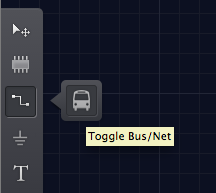
First, switch to the bus tool by clicking the bus icon. Draw where you’d like the bus to be placed. (You’re able to edit this later). The bus will appear as a thicker wire on the schematic:
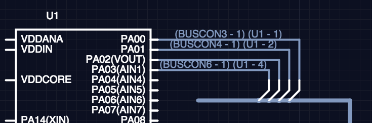
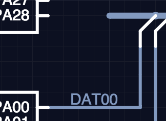
Switch back to the regular net routing tool and start routing nets into the bus. As they touch the bus, the editor automatically adds Bus Connectors to the schematic:
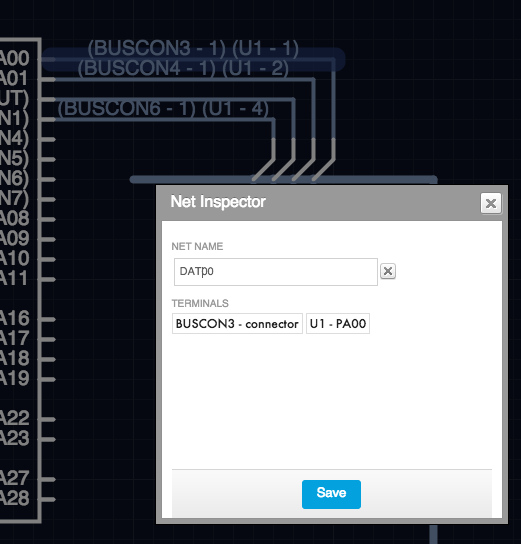
At this point, it’s useful to open the Net Inspector for each net and edit their names to something meaningful. Do this by selecting each net and pressing the i key, or by double-clicking the wire:
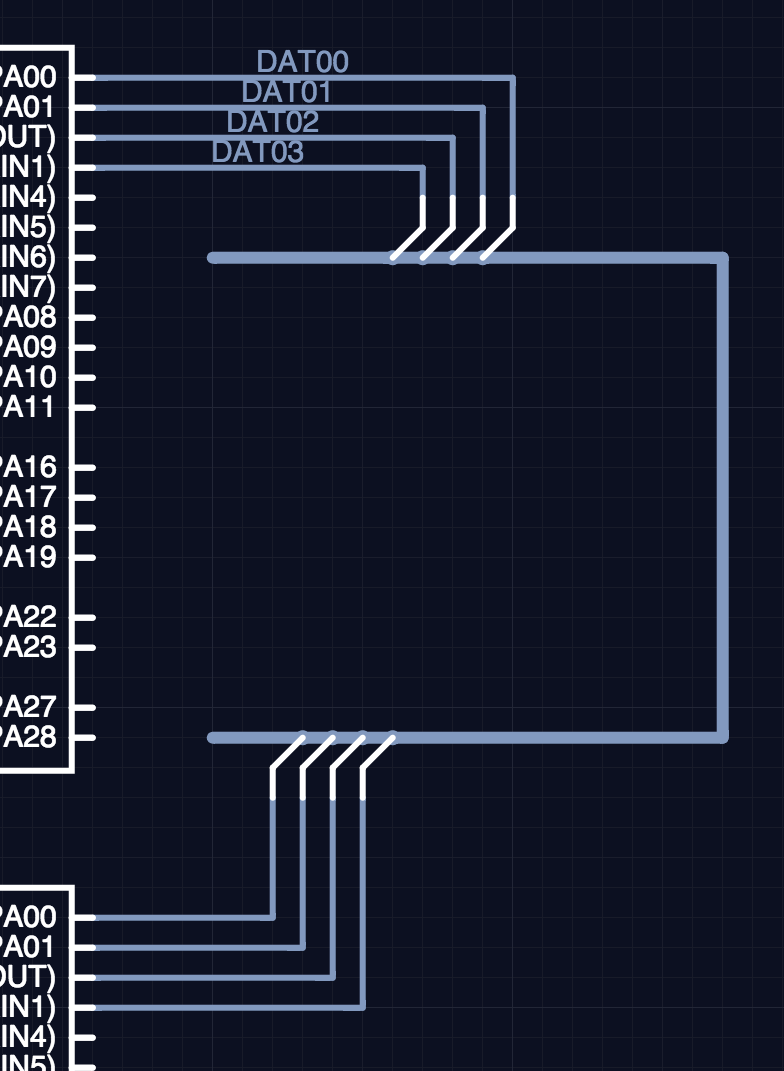
You’ll notice the bus itself now automatically inherits the more meaningful signal name (which you can also edit if you prefer):
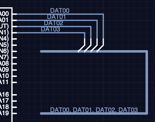
Next, connect your destination nets into the bus. Again, Bus Connectors will automatically be added:
To associate these Bus Connectors with the existing ones, you’ll need to Inspect and edit their association to match the signal name you’d like each to be associated with:
And the connected wire will be automatically renamed:
We should note a few other things:
- You can have an arbitrary number of Bus Connectors per signal on a bus… That is, you can ‘tap’ a signal as many times as you wish.
- Although buses can help clean up complex schematics, they aren’t strictly necessary, since Upverter allows you to simply name two nets the same name, and considers them connected despite whether their wires connect schematic-side. (See: How are you supposed to use a bus? How can you connect a bunch of pins?)
- This format of bus configuration is completely compatible with our OrCAD import feature.
Hope that helps!