
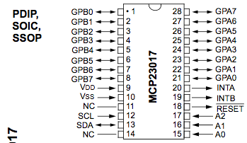
I’m trying to create a schematic for a part (MCP23017). Below is an image from the datasheet:
I created a CSV file for the pins that looks like this and imported it:
1,GPB0
2,GPB1
3,GPB2
4,GPB3
5,GPB4
6,GPB5
7,GPB6
8,GPB7
9,VDD
10,VSS
11,NC/~CS
12,SCL/SCK
13,SDA/SI
14,NC/SO
15,A0
16,A1
17,A2
18,~RESET
19,INTB
20,INTA
21,GPA0
22,GPA1
23,GPA2
24,GPA3
25,GPA4
26,GPA5
27,GPA6
28,GPA7
That created a schematic that looks like this:
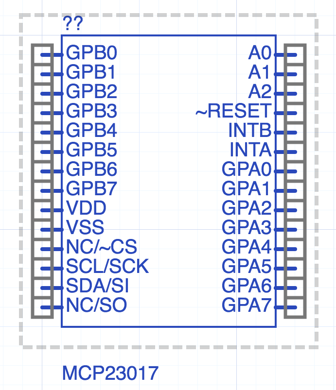
As you can see the pins on the right side (while in the right pin order) are out of order with the images in the datasheet. Is there anyway I could instruct upverter to use a reverse pin order on the right side of the part?