Net wires move suboptimally when moving a part

I find that when I move a part that’s connected to two nets, that the nets move in nearly incomprehensible ways.

For example if I have the following:


   |
   |
   >
   >  R1
   >
   |
   |

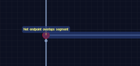
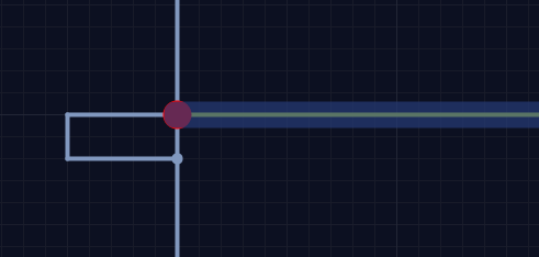
If I select and move R1 to the right, the part will move but the net connections to the top and bottom wires will stay put. This causes the wires connected to R1 to route around in bizarre patterns. This is not expected behavior to me.

I find, also, that once this has happened, I either have to undo or delete all wires on the net.

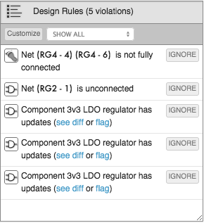
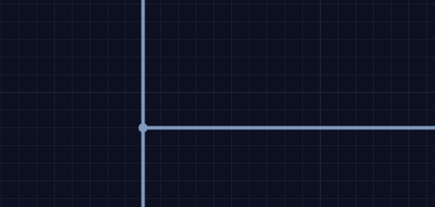
Lastly, I would like a way to turn off the DRC for a 4-way net. I know that some people avoid them. But there are times when they are actually more clear than two 3-way nets near each other. I mean, this is why we put a dot at a net connection.

Thanks.

-Fred

1 Like

Hi Fred,

We’re definitely working on ways to improve the wire placement algorithm. In the meantime, I can help you with the second item for sure: it’s easy to turn off DRCs.

In the Design Rules panel, click the ‘Customize’ button in the top-left:

Then scroll down to the ‘No four-way connections’ design rule, and switch it to ‘OFF’:

In addition to switching rules on and off, this panel also allows to you customize parameters for some of the more sophisticated DRCs like copper-to-copper spacing.

Hope that helps!
Adam

Also, I forgot to mention you can actually shut off our automatic wire routing using this toggle:

(or shift-a)

That will allow you to place wires exactly where you’d like them without interference on our end.

2 Likes

sorry to awaken an old thread, but i think there’s something fundamentally wrong with the schematic trace routing.

here’s the simplest net intersection possible:

if you drag the horizontal trace 1 grid-square upwards, you get this:

and if you, instead, drag it two grid-squares upwards, you get this:

it seems to me that the editor is way too keen to create new segments when just moving the endpoint would work perfectly.

this one behavior pretty much makes it impossible to move traces effectively in the schematic editor. for example, if you move an IC with many connected nets you go from a nicely laid-out schematic to a jumbled mess of weird twisty detours. i find myself just deleting whole nets and starting from scratch rather than fight with this weird behavior - it’s quicker and less frustrating.

1 Like

Hi,

Thanks for bringing this to our notice. We will try to improve net movement in schematic editor and make your experience better.

Yashwanth

I am seeing a similar problem when trying to add a trace to my design. I am connecting to pins 1 and 2 of the part Altera 5M570ZT144C5N. When I use the wire tool and click on the pin then bring the trace straight out it loops around touching other pins and passing under the part body, causing errors and looking terrible.

Is it possible to just turn the feature off and let me route the wire?

Hi SteveT,

For sure - you can always turn off auto net routing using the toggle:

(or shift-a)

In terms of why that routing is occurring: the part in question probably has a pin backward (facing into the symbol). You can edit it yourself, or flag it for concierge review.

Best,
Adam

These errors persist, even after automatic net routing is turned off.

Please implement a “dumb” way to route traces. Clearly the smart algorithm is not working properly.

Moving a part with nets connected is an exercise in futility. I hate to be harsh, but fixing selecting and routing–and not the parts concierge–is what will get me to put money down to use this system.

Thanks.

-Fred

Two years later I don’t see that this has been fixed. Might the issue be worse in some browsers than others? I use Firefox 57+ on MacOS and it is impossible to move components without getting spaghetti net connections (with or without the auto-routing turned off).
As a bare minimum, it would be great to get the ability to manually move the 3-way
connection dot, since it seems that the inability for the automatic algorithm to move
it is a potential cause for the poor behavior.
When dragging a set of components and nets selected via a “box select” towards another component, the nework endpoints slide under the 2nd component and the
dreaded red dots “overlapping segments” show. Haven’t found a good way to
reattach them.

1 Like

I agree. Schematic layout is a pain.

A shame since I enjoy the tool, after some difficulties at the beginning.

I’m having the red dot problem AND when I try to wire a part that is, I don’t know, too close to other parts, it won’t start wiring. It’s really frustrating and I’m already considering cutting my losses and going to another tool.