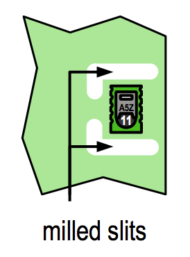
Hi, I’m looking to add cutouts / milled slits to my Upverter board to accommodate a temperature sensor that recommends using them:
Is this possible with Upverter, and if so, what’s the right way to do this?
Thanks!

Hi, I’m looking to add cutouts / milled slits to my Upverter board to accommodate a temperature sensor that recommends using them:
Is this possible with Upverter, and if so, what’s the right way to do this?
Thanks!
You can draw milling slots on Mechanical details layer as you do for the board outline.
Thanks, I had assumed that wasn’t working correctly because the Upverter 3D board preview wasn’t handling cutouts correctly.
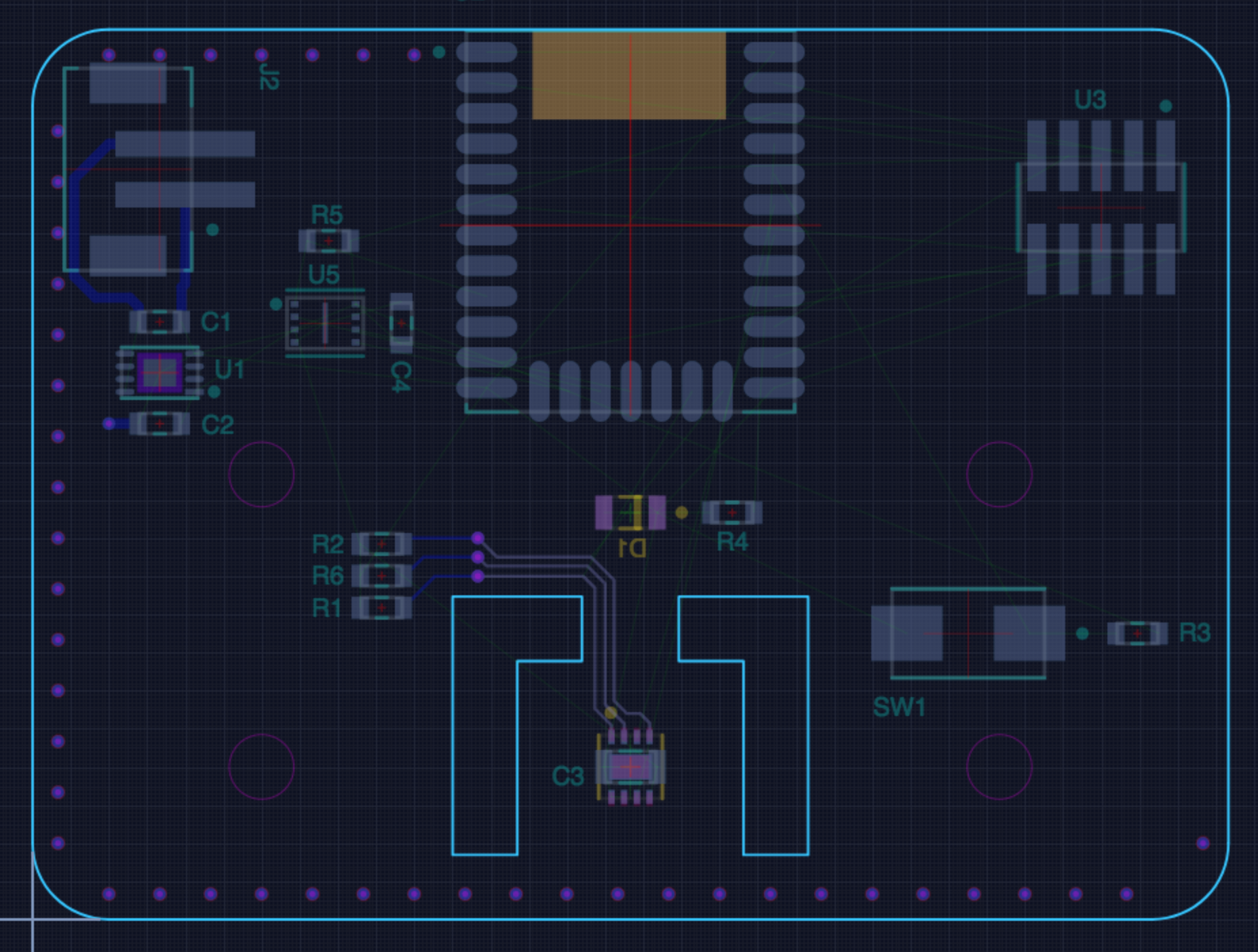
There are a couple of issues with this approach in Upverter. Here’s a preview of an unfinished board which has cutout paths:
It does appear that drawing an additional path inside the board is correctly treated as a cutout by OSHPark when the gerbers are exported:
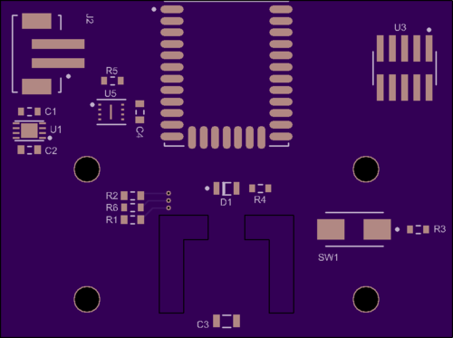
Their docs do say this should be rendered as a black outline and not actually filled in on their preview, so I think this looks correct. However, their docs also say that I should add some text into the cutout area to call it out for the fabricator. Upverter does not allow adding text on the mechanical details layer, so this is not possible.
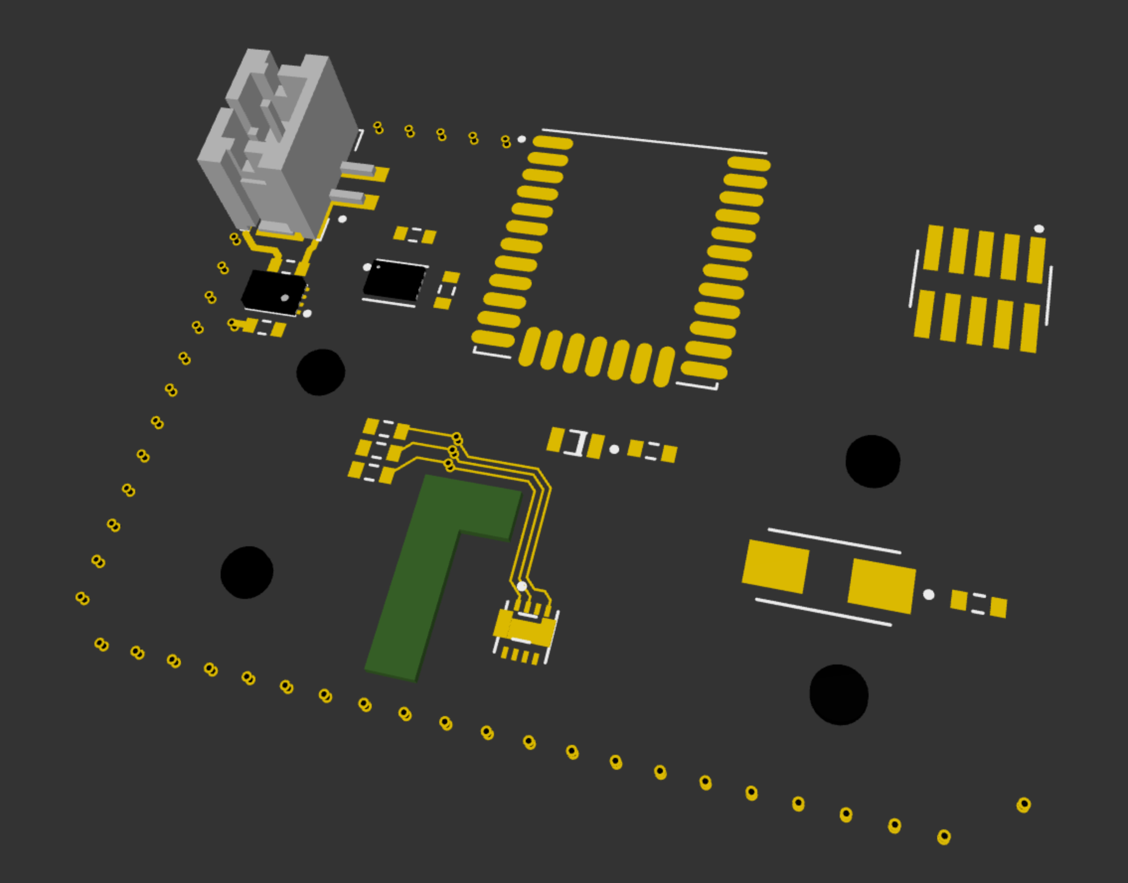
Additionally, when viewing this design with Upverter’s 3D Model feature, these do not appear as cutouts at all. It looks like Upverter randomly picks one of the paths and treats it as the sole board outline:
AFAICT, the same thing is happening when trying to use Upverter’s STEP export feature to view the board in a CAD program.
Are these issues that can be fixed by Upverter?
Same problem here.
Any answer from technical support?
and also pours “spill” into the cutout section
Hi All,
This is a problem with the 3D generation, I have filed a bug to have the engineering team look into a fix.
Thanks,
Michael