
Can a PCB outline be imported into Upverter from DWG or DXF or ? formats? This capability would save a lot time with more complicated board outlines.
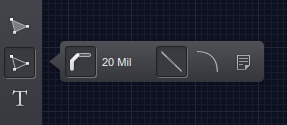
Yep, we support importing board outlines as DXF files. Use the right-most button on the path menu:
Do you support other formats?
I can’t get DXF import to work at all. Sometimes the file fails to load. But always I get an “internal server error” when I attempt to use the file.
I’m bumping this thread because there doesn’t seem to be a more appropriate (and recent) place to put this, and I wanted to document this.
The DXF import functionality seems to be very limited and is not documented at all. I found that I can import some simpler shapes made in Fusion 360, but only if I create a sketch, extrude it, and export the 3D model. If you export the 2D sketch by right-clicking it in the Fusion 360 browser menu and selecting “save as DXF,” the resulting DXF will not work properly with Upverter. Only the exported DXF from an extruded 3D model seems to work. I have no idea why.
I also found that I had to actually draw the sketch in Fusion 360 in order for the resulting export to work. Drawing the outline in another program, exporting it to SVG, and importing the SVG in Fusion 360 will not work.
If you’re trying to create a board outline in Fusion 360 to import to Upverter (via DXF), it looks like the trick is that (in addition to the 3D extrusion detail I mentioned in my previous post), for the best results, the sketch must be created using only simple objects like lines, arcs, and (if necessary) circles. In other words, instead of creating a rectangle shape, create 4 lines in the appropriate positions. You can also use the fillet tool on such a “rectangle” (that’s really just 4 lines) and it will import to Upverter properly without any errors or warnings.
Upverter’s DXF import implementation seems to be quite rudimentary. I’m guessing that if you create the sketch in Fusion 360 using simple objects like lines and arcs, it is exported in the same way, whereas, for instance, a rectangle drawn using the rectangle tool may be represented differently in the file (despite the visible object being exactly the same). None of this is documented anywhere as far as I can find.
As an alternative to importing, I’ve had good success using the Upverter path tool to define board outlines using straight lines and arcs:
- Create an .xls spreadsheet with all the X,Y coordinates (yes- have to use your math geometry skills to get the angles.) Make sure to place origin at lower left.
- Draw a simple triangle path somewhere, which is used as template. Switch from default silkscreen to mechanical layer.
- Edit: Walk around the path entering coordinates and adding arcs as needed.
I presume an imported outline that is defined as a path would be more likely to work.