How to make pours isolate from mechanical layer?

Hi

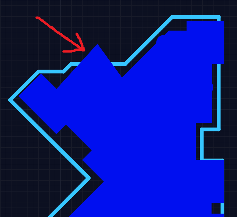
I can’t figure out how to make pours isolate from the edge of the board. They seem to completely ignore the mechanical details layer. This is pretty awkward when I’m trying to make a thin device and use several board-cutout connectors making the board shape quite complex. Any change to position of connector or shape of enclosure means redrawing all of my pours from scratch (since it’s hard to add nodes to the shape). Am I missing something?

Is there a work around? Like should I be drawing my board perimeter on a different layer that the pours respect?

Thanks!

Hi,

I tried to replicate the issue you have raised and was not successful. I did 2 things:

  1. For a sample design, I drew the mechanical outline first and then laid the pour extending outside the mechanical outline. This resulted in Upverter showing me a constraint violation saying “Pour is closer to board edge” and highlighted the board outline in ‘Red’.
  2. I also tried drawing the pour first and then drew the mechanical outline in such a way that the pour is extending outside the board edge. This too resulted in the same constraint violation as above.

To help us understand the problem in depth, can you let me know the workflow you followed to draw the pour and mechanical outline. Also, can you let me know if this is an imported design from Altium, Cadence, etc…

Yashwanth

Hi,

While we do have a Copper-to-Edge design rule, we don’t yet auto-clip pours to the board edge. It’s definitely in the queue!

Best,
Adam

Exactly! Clipping was the word I needed. It’s good to have the constraint but how do you fix it? Delete 4 layers of pours and redo them around all the contours of the board. Eagle automatically clips the pours, it isolates from the mechanical layer the same way it isolates from copper = big time saver.

Thanks for getting this in the queue, look forward to it!

Hi,

For now, to makes things easy while you fix the pour, I would suggest that you use the vertices of the pour to redo them along the contours . This way, you don’t have to delete the pours and redo them all together. Hope this helps.

Yashwanth

Yep, that works if I only need to change the shape a little bit. But if I say, rotate a connector, it’s usually faster to redo the whole thing because as yet, you don’t have a feature to add vertices point-and-click. Without adding vertices, the shapes have to be pretty similar and close to each other to move efficiently.

My workflow with Eagle was to make a large ground pour, a few inches larger than the whole board, for each layer. That’s it. I would never need to think about the pours again throughout the duration of design. They would automatically fix themselves on every change to board shape and size and connectors.