Hi,
A related question.
We got feedback from our board manufacturer/assembler that the 0402 footprint for the “Generic resistor” and “Generic cap” that we used extensively in our design is NOT suitable for manufacturing. The problem is that the 0.5mm distance between pads’ inner edges is too large.
After a long search we found component footprints should be following IPC7351B, which Upverter doesn’t seem to be following for generic components.
When we tried to fork a generic resistor part to change the footprint, we can go through the whole process, see the resulting change on our layout, but after a while (less than an hour) the layout reverts to the previous footprint. When clicking on part in schematic, it represents the
modified footprint. Behavior is very counter intuitive - how can we trust the tool if it automatically reverts parts in layout, but not in the parts dBase (it should do neither)?
What is recommended procedure for creating a part so that we can swap out all our 0402 footprints.
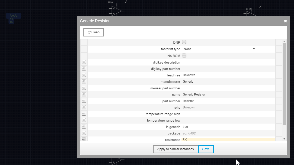
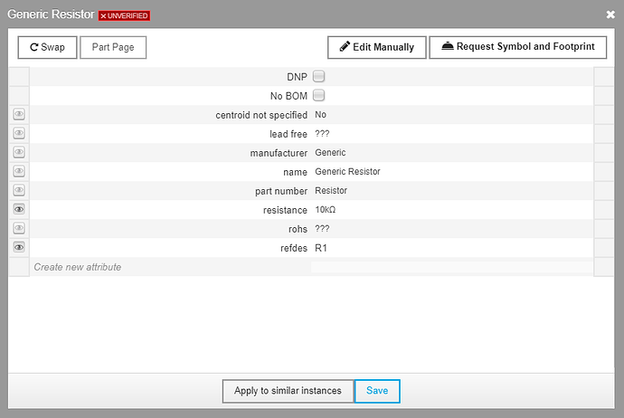
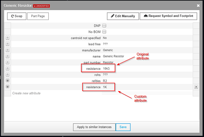
It would be very useful to at least carry over the component values (ie avoid defining a “shadow” resistance value as suggested above. Similarly, creating a completely new part doesn’t appear to allow creating attributes (like resistance, capacitance and voltage) that can be viewed in the schematic and copied over during a swap.
Best of all would of course be if generic parts would be aligned with IPC7351 so we don’t have to fiddle around with generic part variants, but we need a short term workaround until that happens.
Note; IPC7351B isn’t publicly avail, but we found a nice KEMET doc that provides guidance.
KEMET
The above cited inter-pad distance should be 0.28mm per their doc.


