
I designed an 8 channel voltage divider to read 12V-based sensors into a Microchip MCP3008. Resistors are verified SMD 0603 models :
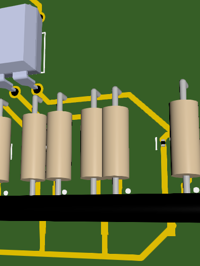
However, in my 3D view they get rendered as two-pin-through-holes resistors. Only one is correct?
The connectors I’ve used in my design were verified too, but they show up as one massive black round bar. Please see snapshot attached:
Have I overlooked something? Is the rest of my design probably OK to start routing?
Any help is appreciated, since I’m a newbie in PCB-design and eager to learn.
TIA for any help!
Cheers,
Mark