
The system got really confused by this. I’m pretty new at it too, so I’m sure that didn’t help.
Ended up practically free forming the board layout because it didn’t know what to do.
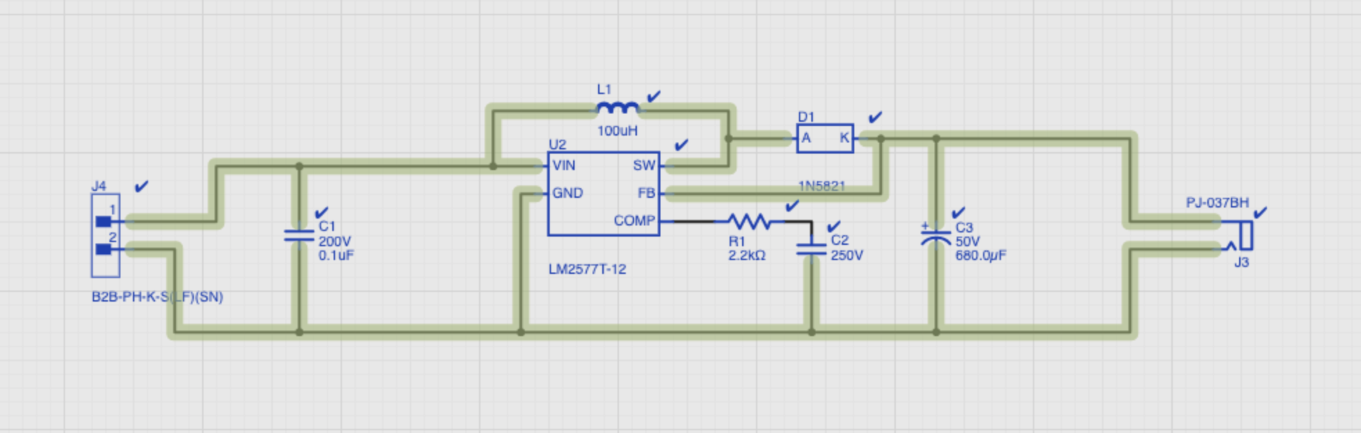
Electrically nothing is wrong.
But Upverter has some constraints that make it look as if this is wrong.
Goto Constraints, and uncheck the following:

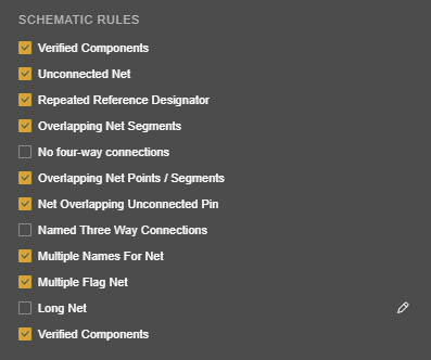
This will disable those highlights.
Yeah, it’s just really confused. I just turned it into an Atmel 28C256 eraser as a companion to my programmer. With a little more work I could put them together. But not with the application as confused as it already is.
I added a switch to the 12V output to initiate the erase. I think I can get away with not debouncing it.
I practically had to free hand the layout because it doesn’t know what to do.
I’m new to board design. I wouldn’t mind a design review.