Albert,
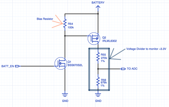
Your circuit concept is good-- only enable the resistor divider to sense the battery voltage when you need to. I just used this approach in a recent design to save power!
I think the bipolar devices aren’t going to help you get an accurate measurement though, the other comments above suggest using MOSFETs and I agree that is a better approach.
The issues I see with the circuit as you’ve got it:
0. It’s not clear what BAT+ is. It would be good to know if you’re trying to sense 3.0-4.2V (Li Poly) or an alkaline cell or lithium primary, or something else.
- VT2 schematic symbol is not drawn as a PNP. I can’t tell if VT2 is wired correctly since the pin numbers aren’t shown. Assuming the emitter of VT2 is connected to Bat+ it would probably work. But you’ve have to figure out the operating point for both VT1 and VT2 and see how they would vary.
- The saturation voltage, Vce(sat), will affect the operating point for VT2. It looks like it’s 700mV max, but it will vary by temp and lot, and if it’s not operating in saturation it’ll be more. This means you’ll have additional voltage drop, and you won’t be measuring Bat+/2, you’ll be measuring ()(Bat+)-VariableVoltage)/2. If you’re looking for a rough voltage level that might be ok, but probably not.
- The effective impedance of the bat_level net is R6||R5, or about 2.5k. This should be ok, but you may need some capacitance on the bat_level net to support the ADC when it muxes that signal onto the ADC sampling cap inside the micro. I would plan for a 1-10nF cap on bat_level and you’ll at least be able to tweak it by changing components if needed. The ST micro may have a recommendation in their datasheet, app note, or reference design for supporting those ADC inputs. It might also need no cap at all, but it’s worth checking. If you include the cap, you need to figure out how much settling time you need after turning the divider on since it’ll take time to charge the cap (not much, but micro’s can be fast!)
I would recommend (as the other posters have) using a single MOSFET. You can even use an Nch MOSFET if you chose the right part with low threshold voltages, with the resulting divider being more like 3:1 or 4:1 instead of 2:1. I think the 2N7002 might be ok, but it’s threshold voltage is 2.5V max, so you’d need to make sure the sense node never got above Vcc-2.5 or the MOSFET would start to turn off! Something the AO3414, with 1.8V threshold might be better.
Since you’re turing it on and off, and it’s mostly off, it’s probably better to stick with lower value resistors (10-50k) as opposed to the >250k R’s suggested above – they can increase the noise susceptibility on that node and cause other problems for you.
I would post an image of what I’m talking about but apparently I’m a new user and can’t do such things.
Basically, replace VT2 with AO3414 or equivalent. Directly drive the gate of the MOSFET with your BM_en signal. Add a pulldown (100k or so) to the gate. Add a cap to bat_level. You won’t need R9, R7, R3, or VT1.
[EDIT: the top resistor of the divider needs to be on the high side of the MOSFET!]
Dave
