
Gotta love it when our users build useful things that work.
I reached out to our users Julian Binder and Ian Hartwig about their Razor18 BLDC Power Stage project.
The board was a core part of our project for the Build18 Hackathon at Carnegie Mellon University. This hackathon happens the first week of the spring semester (late Jan.) every year in our Electrical and Computer Engineering department. More information can be found on Build18, but the gist is student teams of up to 4 can apply with a project to get up to $250 of parts ordered ahead of time. Project assembly should happen Sun.-Fri. of the build week, but planning ahead and ordering boards is encouraged. We ordered our boards ahead of time through OSHPark.
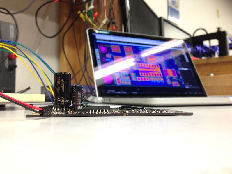
Our project was to build a high-current, electrically isolated, senseless brushless motor controller. This is the kind of motor commonly found on RC airplanes and quadcopters. Where these systems are typical 11V/30A we were designing for 24V at 100A. The demo platform was meant to be a Razor scooter with a large (Turnigy Aerodrive SK3) brushless motor mounted on the back. This type of controller consists of a set of FETs for switching battery power onto the motor wires, drivers for the FETs (we used charge-pump based high side NFET drivers for efficiency), feedback for the back EMF to sense motor speed/position, and (in our case) optocoupler isolation on the data lines to the microcontroller. Since this board only has the power/sensing circuits, it is meant to be paired up with a microcontroller demo board like an ATMega32U4 breakout or STM32F0 Discovery Board. The back of the board exposes large copper areas with no components so that a huge heatsink can cover it.
In our case, we completed population and bring up of the hardware you can see in the Upverter designs. We didn’t finish the firmware that handles the control signals, so it doesn’t actually work as a motor controller yet. At the last minute, we swapped an off the shelf motor controller onto the scooter, which is what you see working in the last video in that photo album. The board hardware is functional with minimal changes, as it was designed to be configurable. The high side drivers need a higher Vdd than expected, and the optocouplers are connected in a (surprise) inverter configuration, so I would fix those if I do another board spin.
They even powered a scooter!
We’re always looking for new posts to feature in our newsletter, and blog – If you’d like to be featured, send a photo of your product, design URL, and a description to yusef@upverter.com