
I imported a design from Eagle and I don’t see the unrouted traces. I also have found that the schematic symbols are not exactly on the grid. So, I can’t cleanly connect the net wires between parts. Are these problems related?
Do you have the link to the design?
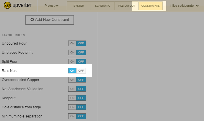
Are you referring to rats nest when you say “unrouted traces”? If so, it’s possible that they are turned off. They are controlled by a design rule that you can find in the constraints tool, labelled “Rats Nest” under the section “Layout Rules”.
https://upverter.com/hackmeopen/a146fd949ed48210/Colr/
Here’s the link. Rats Nest appears to be on as far as I can tell.
When rats nest is turned on in the constraints tool, it should look similar to the screenshot below:
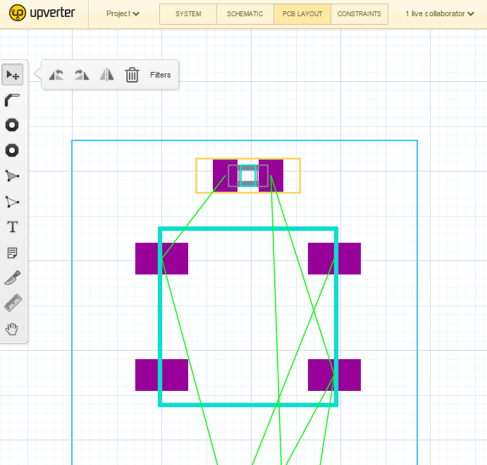
And in the design, they show up as green lines.
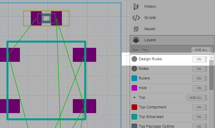
If they still don’t show up, double-check that the design rules layer is not hidden.
Let us know if you still have trouble turning on the rats nest.
Re: your schematic not aligning to the grid; that is a bug on our end. I’ve filed the issue and a developer will take a look at the importer as soon as possible.
1 Like
Excellent. Thank you.
FYI, this occurs because we’ve switched off all design rules by default for imported designs. Typically, projects created in other software have been designed under a different set of assumptions and usually result in a huge number of violations against the default settings of our design rules.
Switching off the rules by default allows you to see the imported design without sweating about everything we might mistakenly think is an error.