Old School EEPROM Programmer

I am a hardware beginner, so please don’t expect much. I got this circuit to work on a breadboard (with some changes) and am now trying to turn it into a cape that I can plug into my Beaglebone Black.

My goal is to build a tool that will allow me to program old-school EEPROMs. This is step 1 in building a single-board Z-80 computer, which will use the EEPROM.

Please let me know how I can do better, especially the board layout.

Thanks!

https://upverter.com/cheinan/062284316b433315/BeagleBone-Black-28C256-EEPROM-Programmer/

4 Likes

This is a fantastic start, Cheinan! I’m a big fan of wire management, so flags would’ve been the first thing I’d recommend.

You’ve beaten me to it, though!

This is a fantastic start.

Hey cheinan, I had a look at your design and electrically, it looks like it should all work. I have a few comments on manufacturability, though.

I’d recommend increasing the width of your 6 mil traces. 6 mil is the absolute minimum for some of the less expensive services like OSH Park and Seeed’s Fusion PCB, but if you could bump those traces up to 10 or 12 mil, you could have much more confidence in it being correctly manufactured.

I’d also suggest increasing the size of the ground pours on both sides of the board. They could fill the entire side of the board, really. I don’t know how this affects manufacturability at a real PCB fab, but certainly you should do this if you wanted to mill your board or etch it at home. For a milled board, you wouldn’t want to waste time and your drill bit on milling out copper that doesn’t need to be removed. For a home-etched board, I find you get better results when the copper to be removed is evenly distributed across the board and fairly sparse.

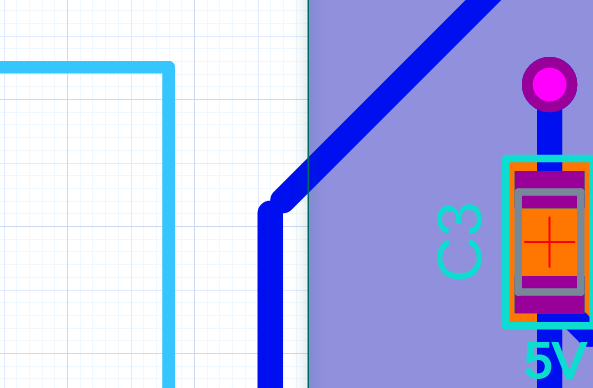
One final point is that the 3.3V trace near the cutout for the USB connector isn’t quite connected - see below:

Looks great, though! I actually need a EEPROM programmer just like this for a Z80 project I’m working on, so I’m glad you’re publishing it!

Thank you Yusef and Alex for the tips and encouragement.

Originally I tried to make all the traces 10 mils, but failed to get these traces from the outer pins of the two big connectors on the edges into the middle of the board. That was before I learned about toggling between grid and guide snapping with the shift key and that I could have 10 mil traces with 6 mil clearance.

So I set a design rule that all traces must be at least 10 mils and success!

I also tried very hard to get a pour on the front copper, but I kept getting islands. I couldn’t figure out how to get rid of the islands by changing the pour min thickness and clearance. If I increased the min thickness, the islands decreased, but then “necks” in the pour would separate and I would get new islands. I tried to get pours to overlap, but couldn’t do that either. I wanted to overlap the pours so I could put simple rectangular pours where I wanted rather than trying to manipulate a huge board-wide pour. So, pour-frustration :-/

As to pushing the pours out to the board edges, I’ll give it a try. I’m planning to fab at OSH Park and I think they want no copper within 15 mils of the edge, so I’ll see how close I can get it. A cool feature for Upverter would be “pour to within X distance of the mechanical edge.”

Alex, how you saw that under-connected trace, I have no idea, but thanks. I fixed it.

1 Like

Glad to be of help!

10/10 would trace again.